|
|
||||||||||||||||
|
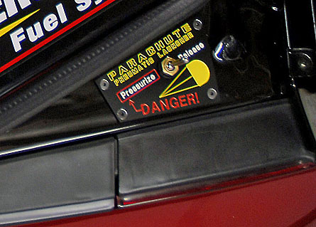
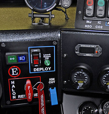
A parachute system is not just a luxury or add on. Under NHRA rules you must have one installed once you get to certain mph trap speeds. You don't have to use it, just have it on the car (which is why you see a lot of cars with them on but not pulling them). Installation is a muti-step process and fairly involved. Proper installation is extremely important from a safety standpoint. Improper installation can cause the driver to lose control of the car. We use a 420 STROUD parachute. We also use a pneumatic launcher rather than the spring style. While we have a manual release lever to deploy we also use an electric switch on the dash so the driver doesn't have to locate the lever. The switch is much faster and basically throws the lever by charging an air cylinder that the lever is mounted on up on the roof of the cabin (photos later in the page). This lever pulls the cable out of the chute stop and the parachute is then launched out and away from the car. So the parachute system has several parts. The mount to the car, which has to be A) strong , and B) perfectly centered so it doesn't throw the car off centerline or lift up, etc. Then the release system of which we have two - manual and pneumatic. The launch system is either spring loaded or pneumatic launcher. We use the latter. The parachute is kept unpacked and hanging in the shop and not packed until needed at the race track. Parachutes should never be stored in the bag.
|
|
|
|
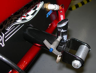
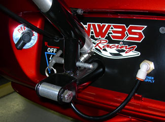
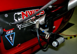
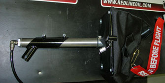
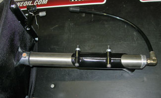
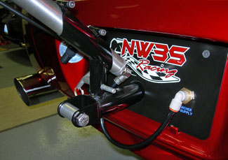
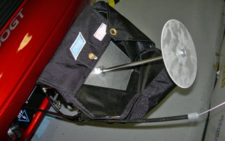
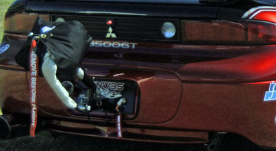
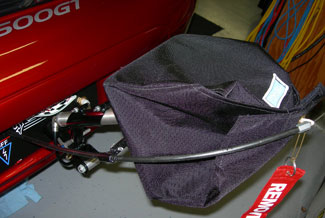
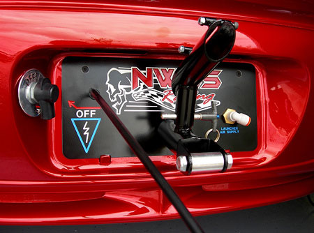
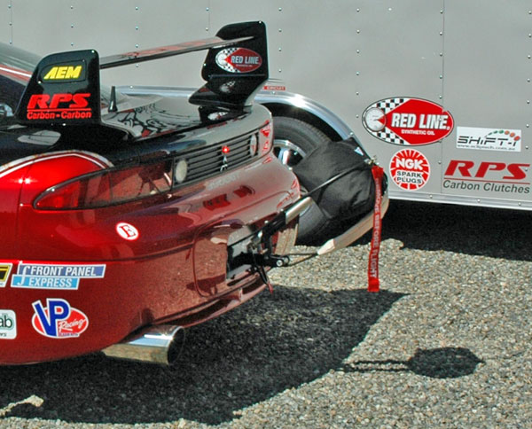
Here are some photos showing the mount and the rear of the car where the mount goes into the rear bumper and connects to the frame of the car. It is attached to the main rear crash bar hard points of the vehicle. The mount, plate and connections were all fabricated or completed in-house. The parachute itself is packed into a bag that is installed into the launcher bag shown on the right. This is the pneumatic launcher tube (silver tube part). The parachute is under pressure the entire time it is in the bag when ready to launch. The parachute end is attached to the round roller shown on the left with the bolt at the end of the car mount which is exactly centered for the pull point.
Also shown is the pneumatic outlet for charging the launch cylinder (compressed gas fitting right lower of the rear 'plate').
On the right is the launch tube fully expanded (deployed)
CLICK the photos for larger view |
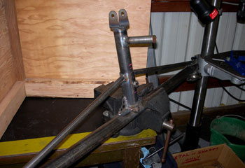
Here is the mount before installation inside the rear bumper.
Click image for alternate view.
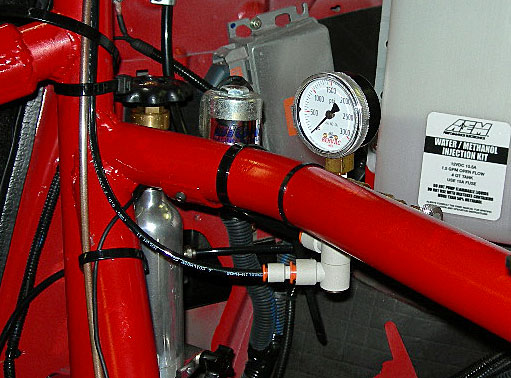
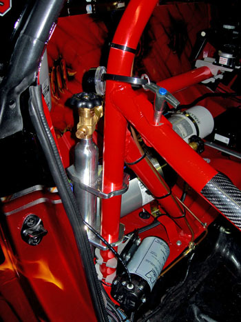
The small silver tank mounted to the roll bar shown on the right is the pneumatic gas supply for the air launcher. It contains pressurized CO2 and is connected to a regulator. From there a line goes to the rear of the car for the launch tube as well as up to the roof for the launch lever controller.
|
 |
|
|
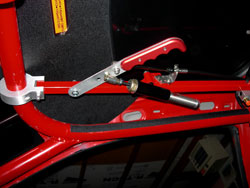
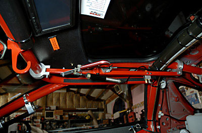
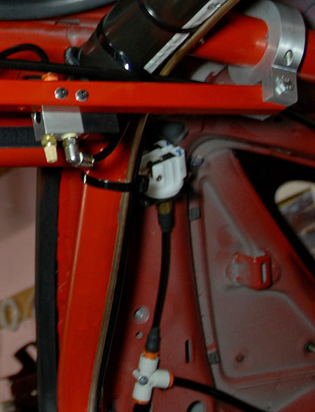
Here are two views of the parachute launch lever. The driver does not have to reach up here as it is all automated from the switch on the dash as shown previously.
However, if there is any failure whatsoever the drive CAN reach up and manually throw the lever thereby releasing the parachute. This is a safety feature so that no air pressure or other failure can prevent launching the parachute.
Click the image to see a close of view of the manual release and lever arrangement.
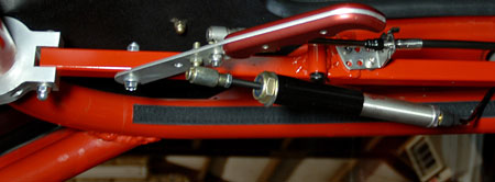
Below is a sectional view of the lever system |
The lever showing the pivot point, cable connection, and the pneumatic cylinder attachment to the manual lever.
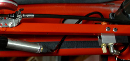
The cable connection point and the electric air activation switch with exhaust filter.
Activation pneumatic switch and showing the pressure sensor / monitor and the wye connection with supply going back to trunk for launcher supply.
|
|
|
Here is the 3000GT race car in a paddock with the parachute packed and ready.
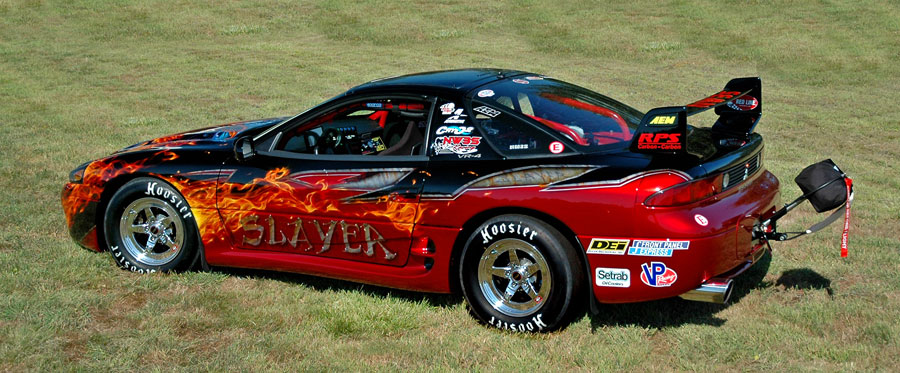
click image for high resolution view in new window
 |
|
